Flow control at microscale: Nanofluidics, microfluidics and millifluidics

“Nanofluidics is the study of the behavior, manipulation, and control of fluids flow that are confined to structures of nanometer (typically 1-100 nm) characteristic dimensions (1 nm = 10-9 m). Fluids confined in these structures exhibit physical behaviors not observed in larger structures, such as those of micrometer dimensions and above, because the characteristic physical scaling lengths of the fluid (e.g. Debye length, hydrodynamic radius) very closely coincide with the dimensions of the nanostructure itself.” [1]
“Microfluidic devices are characterized by channels with diameters ranging roughly between 100 nm and 100 microns, often involving particles with diameters ranging roughly from 10 nm to 10 microns. At these length scales, the Reynolds number is low and the flow is usually laminar, but the mass transfer Peclet number is often large, leading to unique microfluidic mixing regimes.” [2]
Millifluidics refers to systems using flows in capillaries showing an internal cross section above 1mm. The limit of millifluidics with conventional fluidics is when the Reynolds number approaches the value 1 where turbulences cannot be neglected anymore.
Microfluidics flow control: introduction to micro-flows
Navier-Stokes Equation
Microfluidics flows are governed by the Navier Stokes equations [3].
This equation arise from Newton’s 2nd law applied to fluids:
Forces here are forces per unit volume. fgravity is the gravity force, fpressure is the pressure force and fviscous is the viscous force, u is the fluid velocity and ρ is the density.
The acceleration term can be developed in respectively convective term (time-independent space variation) and time variation (calculation details in [4]):


where g is gravity, Fpressure is the total pressure force, V is the fluid volume and p is the pressure.
For an unidirectional fluid (along x axis), viscous force can be calculated as follows [4], [6]:


For an incompressible, unidirectional, steady and newtonian micro-fluid, several simplifications can be made:
- gravity can be neglected
- convective term with advection operator [7] is null [8], because of unidirectional fluid property (speed vector components in other directions are null) and mass conservation (div(u)=0, [9])

- fluid is steady so


Pressure forces balances viscous forces.
Pressure driven micro-flows
The former equation can be solved for various shapes of microchannels (10). In the case of cylindrical microchannels, a parabolic flow develops and the relation between pressure and flow rate is described by the Hagen-Poiseuille equation (11):

Where ΔP is the pressure drop between the two ends of the channel, L is the total length of channel, Q is the volumetric flow rate, r is the radius of the channel (or D the diameter) and v is the average flow velocity across the section.
In the case of square channel or low aspect ratio rectangular channels, a good approximation (0.7% in worst cases) of the relation between pressure and flow rate is given by (12)
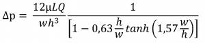
where h is the channel cross sections height and w is the channel cross sections width.
Fluidic analogy to electrical circuit: concept of fluidic resistance
The average flow rate of a liquid within a micro- or nanofluidic channel is proportional to the pressure gradient imposed on both ends of the capillary. As a consequence, the Hagen-Poiseuille equation can be rewritten as a classical Ohm’s law [13]:

The fluidic resistance will depend on the geometry of the cross section (6). However, for most of the geometries, the fluidic resistance can be predicted by the following equation where h is the channel cross sections height and w is the channel cross sections width:
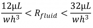
The left side of the equation should be taken as an approximation when 10h<w, the right side should be taken as an approximation when 2h>w. For an intermediate case, an average of both approximations can be used.
The fluidic resistance can also be calculated for micro- and nanofluidic networks using the same method as for electrical circuits (13) and the flow rates can be deduced in the different portions of the microfluidic device, as an example using the classical Kirchhoff equations (7). This concept can be advantageously used in microfluidics by using capillary tubing that will act as flow restrictors and let the user reach and work with low flow rates, even with a low fluidic resistance setup.
Effective section calculation
The effective section Seffect is used to calculate the typical pressure drop as a function of the flow rate in 1cm long microchannels. For a straight channel of 1 cm used with water based liquid, it can be approximated by the product of the channel cross sections height h and the channel cross sections width w (the square of the radius in the case of cylindrical channel).
For complex micro- or nanofluidics networks, or when viscous liquids are used, the effective section can also be derived from the fluidic resistance calculation. Using the classical rules exposed here before, it is possible to get a first approximation of the global effective section of the microfluidic device using the total fluidic resistance Rtotal and the following equation:

Flow control microfluidics: Systems for external flow control
There are three main classes of flow control systems for microfluidics and nanofluidics.
Some systems use a pressure difference to control the flow rate (hydrostatic or pressure generators), whereas other systems can directly impose a flow rate (syringe pumps). Finally, liquid pumps and electro-osmotic pumps can be used to generate a liquid flow that will depend on the fluidic resistance of the device.

Hydrostatic pressure
Hydrostatic pressure is the simplest way to generate controlled flows in a microfluidic system. The pressure difference is obtained by varying the altitude of the liquid to atmosphere interface in different reservoirs. For water based liquids, the difference of 1cm corresponds to 1mBar, which limits the resolution of this technique to 0,1mBar and the maximal pressure to 100mbar (1m of difference of height).
This technique is also limited by the Laplace pressure that develops at the air-liquid interface and which depends on the affinity between the liquid, the atmosphere and the reservoir and on the reservoir shape. From a few tens of µBars in large reservoirs, this unpredictable overpressure can represent several millibars in hydrophobic or hydrophilic reservoirs showing a narrow cross-section.
This system is also limited by the lack of dynamic control in the applied pressure within microchannels making any change in pressure parameter quite tricky to apply.
Finally, another limitation of this type of pressure control is the progressive change in the pressure drop as the liquid flow through one reservoir to the other, resulting in a linear decrease of the pressure drop with time.
Pressure generators
The simplest pressure generator is composed of a pressure source (compressor, bottle), a static membrane pressure regulator and a manometer to monitor the pressure value as regard to the atmosphere pressure. The robustness and precision of these systems highly depend on a good compatibility of all the components.
The major drawback of these systems is the fastness of response that is limited by the mechanic deformation of the tubing. But this ability to deform can be used in a smart way: tubing can easily be added to your setup to absorb and dampen the flow rate fluctuations before they affect your experiment. So a pressure generator can be highly responsive by simply adjusting the experimental set-up. Another possibility to quickly change the pressure is the use of several pressure generators with a pressure multiplexor that can be computer-controlled and allows to switch from one pressure to another in a few µs.
Another possibility is to control the pressure using a set of electrovalves enslaved electronically to a pressure sensor. The advantage of this technology is the quick response that can be achieved with microvalves. The major drawback of two-valve electronic pressure generators is the fluctuating pressure that is generated (a constant pressure is ensured by an alternative opening of the positive pressure vs. exhaust electrovalves so that the faster the system, the higher these fluctuations will be ).
This type of pressure regulator is well fitted for applications requiring sophisticated pressure patterns (gradient or sinusoidal pressure variation for example), precision and fastness but may be fragile compared to static pressure regulators when overpressure or liquids enter the system.
Pressure generators can also be associated with flow sensors to ensure a flow-rate control instead of a pressure control (in this case a flowrate feedback control is integrated to the pressure generator).
Syringe pumps
Syringe pumps are the first flow controller used in microfluidics. These systems were first developed for perfusion systems in the medical field and were adopted by microfluidics scientists in their early developments. The main advantage of syringe pumps is their capability to control the flow rate across microchannels independently of the fluidic resistance (the pressure automatically adapts to maintain the flow rate).
The main drawback of syringe pumps is the development of pulsatile flows at low flow rates and the time required to stabilize the effective flow rates when the compliance of the tubing is not negligible.
To address these issues, we developed a Syringe Pump Stabilizer Add-on Kit designed to absorb and dampen the flow rate fluctuations before they affect your experiment, and a Syringe Pump Responsiveness Add-on Kit that can easily be added to your setup to quickly and efficiently forward your flow rate instructions, allowing you to improve settling time.
For example, when a tube of 10cm long and 0,5mm in diameter shows a 0,1% change in its internal diameter (+0,5µm) because of a pressure rise of 1bar (flow rate of 0,03 µL in a microfluidic device of effective section of 10µm²), 1 min is necessary to obtain 66% of the final flow rate (5 min to get 99% and 10 min to get 99,99%).
A selection of syringe pumps can be found at Darwin Microfluidics, an official partner of Elveflow.
Liquid pumps (peristaltic, piezo-electric)

Liquid pumps cannot be modeled as perfect flow rate generators since the back pressure lowers the flow rate. Usually, the flow rate Q is expressed linearly as a function of the backpressure ∆Pback using a linear relation of the following type:
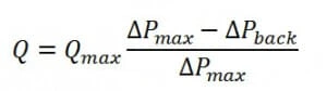
Where Qmax is the flow rate achieved when the pump is used without any exit fluidic resistance and ∆Pmax is the maximal backpressure that the pump can compete with.
A wide range of technologies can be used. Among them, there are:
- peristaltic pumps that show the main advantage of using interchangeable flexible tubes (limiting the contamination problems) and are fitted for large flow rates applications.
- piezo-electric pumps which are the most compact pumps and can be used for intermediate flow rates (µL).
The control of flow rate requires the enslavement of the pump to a flow rate sensor and fluctuations can be observed for lower flow rates. HPLC pumps integrate all of these components while minimizing the fluctuations but reveal themselves as an expensive system for flow rate control.
Electro-osmotic pumps

Electro-osmotic pumps do not show flow fluctuation problems since they are based on the electrical pumping of liquid through nanoporous materials. These systems can also withstand larger back pressures but require to work with low conductivity liquids and suffer from a lack of reproducibility.
Applications of microfluidics flow control
Flow control microfluidics: Chemical synthesis
“A microchannel reactor is a device in which chemical reactions take place in a confinement with typical lateral dimensions below 1 mm; the most typical form of such confinement are microchannels. Microreactors are studied in the field of micro process engineering, together with other devices (such as micro heat exchangers) in which physical processes occur. The microreactor is usually a continuous flow reactor (contrast with/to a batch reactor). Microreactors offer many advantages over conventional scale reactors, including vast improvements in energy efficiency, reaction speed and yield, safety, reliability, scalability, on-site/on-demand production, and a much finer degree of process control.” (15) For more information on the chemical applications of microfluidics click here.
Flow control microfluidics: Separation and analysis
“Many chemical and biochemical analysis methods involve performing a sequence of processes that can be broadly classified in terms of sample preparation, reactions, and product analysis. Since the reaction products often contain mixtures of multiple chemical species, subsequent analytical steps must be capable of separating and identifying the individual components. Electrophoresis, which relies on inducing detectable differences in migration behavior between charged species under the influence of an applied electric field, has proven to be a highly versatile analytical technique owing to a favorable combination of characteristics including relatively simple hardware design and compatibility with a wide range of analytes including biological macromolecules (e.g., DNA, proteins).” (16)
Flow control microfluidics for Biodetection
Biodetection refers to the field of medical diagnostics, food quality and biological warfare detection. The aim of microfluidic detection devices is to miniaturize and parallelize classical immunologic and genomic detection assays.
Micro and nanofluidic devices dedicated to biodetection can be divided in two major classes:
- sample preparation devices in which a preconditioning of the sample can be obtained (matrix change, preconcentration, cell lysis, purification, etc…)
- biosensors devices in which the presence of the targeted analyte is transformed into a physical signal (e.g. electrical or optical).
On-chip real time PCR, enzyme or classic ELISA immuno-sensors and microarrays are among the most promising technologies for biological agent or markers detection.
Flow control microfluidics for single cell biology
“Microfluidics is a well understood physics domain and can now be used to develop tools for cell biology. By simply miniaturizing macroscopic systems and taking advantage of the possibility of massive parallel processing, some microfluidic chips enable high-throughput biological experiments. Specific effects of laminar flow at the micron-scale also enable spatial control of liquid composition at subcellular resolution, fast media and temperature control, and single cell handling and analysis. Microfluidic technology enables studies of cell behavior from single- to multi-cellular organism level with precise and localized application of experimental conditions unreachable using macroscopic tools.” (17)
Flow control for droplet microfluidics
Multiphase flows generate a high interest in microfluidics as the laminar flows facilitate the generation of monodisperse droplets. Emulsions and double emulsions can be used for nanoparticle synthesis, drug microencapsulation (lipid vesicles), and active substance encapsulation. Microdroplets can also be used as single microreactors in biodetection systems. The amplification of single DNA strands can be obtained to increase the biodetection sensitivity. Simple yet efficient proofs of concepts concerning droplets in microfluidics have been made using microfluidic Tees or Crosses that are very easy to implement.
“Alternatives to the above closed-channel continuous-flow systems include novel open structures, where discrete, independently controllable droplets are manipulated on a substrate using electrowetting. Following the analogy of digital microelectronics, this approach is referred to as digital microfluidics.” (18)
Flow control for Microfluidics rheometry
Working with low Reynolds numbers allows to properly investigate viscous liquids, especially non linear visquous effects. A number of microfluidic rheometry systems have been investigated and present an alternative to conventional characterization methods. The study of fluid transport across micro or nanofluidic porous media is also of high interest for oil recovery applications.
Finally, a number a fundamental questions around the slip velocity at the solid-liquid interface can also be investigated using microfluidic devices together with particle velocimetry techniques.
Flow control microfluidics for Optofluidics
“Optofluidics refers to manipulation of light using fluids, or vice-versa, on the micro to nanometer scale. By taking advantage of the microfluidic manipulation, the optical properties of the fluids can be precisely and flexibly controlled to realize reconfigurable optical components which are otherwise difficult or impossible to implement with solid-state technology. In addition, the unique behavior of fluids on micro/nano scale has given rise to the possibility to manipulate the fluid using light.” (19)
For more microfluidic reviews, you can have a look here: «Microfluidics reviews». The photos in this article come from the Elveflow® data bank, Wikipedia or elsewhere if precised. Article written by Adrien Plecis and Timothée Houssin.
References
- https://en.wikipedia.org/wiki/Nanofluidics. [En ligne]
- [En ligne]
- https://en.wikipedia.org/wiki/Navier%E2%80%93Stokes_equations. [En ligne]
- https://elveflow.com/wp-content/uploads/2020/03/Microfluidic-Dynamics.pdf
- Lautrup, B. Physics of Continuous Matter, Second Edition: Exotic and Everyday Phenomena in the Macroscopic World. (CRC Press, 2011).
- https://en.wikipedia.org/wiki/Material_derivative
- Kirby, B. J. Micro- and Nanoscale Fluid Mechanics: Transport in Microfluidic Devices. (Cambridge University Press, 2010).
- https://en.wikipedia.org/wiki/Continuity_equation#Fluid_dynamics
- Page elvesys : solution of the Navier-Stockes equation in various microchannel shapes and geometries.
- https://en.wikipedia.org/wiki/Hagen%E2%80%93Poiseuille_equation.
- Pressure Drop of Fully-Developed, Laminar Flow in Microchannels of Arbitrary Cross-Section. M. Bahrami, M. M. Yovanovich, J. R. Culham. s.l. : Transactions of the ASME, Vol. Journal of Fluids Engineering,1044 / Vol. 128, SEPTEMBER 2006. [En ligne]
- A.Ajdari – Steady flows in networks of microfluidic channels: building on the analogy with electrical circuit – Comptes rendus physique – 2004. [En ligne]
- https://en.wikipedia.org/wiki/Kirchhoff’s_circuit_laws. [En ligne]
- https://en.wikipedia.org/wiki/Microreactor. [En ligne]
- MICROFLUIDIC TECHNOLOGIES FOR MINIATURIZED ANALYSIS SYSTEMS, 2007, 393-438, DOI: 10.1007/978-0-387-68424-6_10. [En ligne]
- Microfluidic tools for cell biological research, G. Velve-Casquillas et al, Nanotoday, Volume 5, Issue 1, February 2010, Pages 28-47. [En ligne]
- https://en.wikipedia.org/wiki/Microfluidics#Digital_microfluidics
- https://acoustofluidics.pratt.duke.edu/
For more information or Technical discussion

Microfluidics knowledge
Do you want tips on how to best set up your microfluidic experiment? Do you need inspiration or a different angle to take on your specific problem? Well, we probably have an application note just for you, feel free to check them out!


 Job
Job Collaborations
 Customer
 Other
Other