pH control in microfluidics: a review
Introduction to pH control in microfluidics
The ultimate goal in microfluidics is to achieve the so-called lab-on-a-chip, i.e., integrate all those activities usually performed in a laboratory within a single microfluidic chip. In recent years, giant steps in this direction have been made: microfluidic devices are used in a handful of applications, ranging from physics to biomedicine.
Moreover, the implantation of several functions in a single chip not only gives obvious advantages over portability and costs, but miniaturization also allows the study of biochemical phenomena down to the cellular scale.
These features catalyzed researchers’ interest in applying microfluidics in cell culture-related investigations. Indeed, using a microfluidic chip allows both to grow the sample and perform the desired observations within the same platform. Cell culture in microfluidics, however, does not come without challenges.
One of the most critical issues in this field is that cells are avulsed from the outside world by the microfluidic chip, preventing direct microenvironment monitoring. In this regard, pH is one of the most significant parameters to probe inside culture chambers. Indeed, cells can influence their surroundings, e.g., producing carbon dioxide and lactate during respiration, which acidify the microenvironment of the culture chamber.
The effects of these natural processes are made much more critical due to the meager (~µL) amount of liquids contained in a typical microfluidic culture chamber.
Therefore, being able to dynamically measure and even control pH levels inside a microfluidic device is a crucial topic within microfluidics applications. In the following section, a few methods to achieve pH monitoring in microfluidic devices will be briefly presented; in addition, the supplementary notes describe the basic principles of solid-state sensors for pH measurements integrated into microfluidic devices.
Optical pH control and monitoring in microfluidics
Most current cell culture media contains simple pH indicators, such as phenol red. The molecules of these compounds are characterized by the fact that they can change color depending on the pH level of the surrounding environment. This feature allows a simple yet rough monitoring of medium pH. However, to perform quantitative measurements by this method, a relatively long path is needed for light to be absorbed, which is different for microfluidic devices.
Magnusson et al. [1] developed a technique that enables overcoming this issue by implementing a non-absorbing part in the imaging area, thus allowing it to perform quantitative and precise pH measurements. A prerequisite of this technique is the need to intensely calibrate the light source with a non-absorbing liquid before any measurements.
This technique’s main advantage lies in its only requiring standard equipment, such as transmitted-light microscopes and a digital camera with a CCD sensor, which can be found in most biomedical research laboratories. The following section presents the basic theoretical principles underlying this technique.
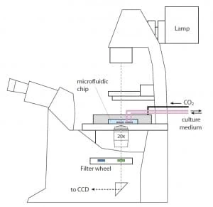
As shown in Figure 1, the light from the microfluidic device is collected by the objective in the microscope and then filtered by the selected bandpass; the resulting image is thus transmitted to the camera’s CCD sensor. When the absorption medium, i.e., a solution containing phenol red, is added, the intensity of the light reaching the camera will be of the form:
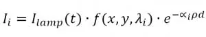
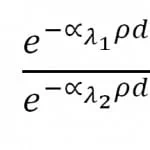
Where λi are the two absorption wavelengths of phenol red (acid and basic form), ∝i are the corresponding absorption coefficients, ρ is the phenol red concentration, and d is the thickness of the microfluidic chamber. As the aim is to determine the ratio between the two absorption factors, calibration measurements are performed without phenol red media to neglect the dependency from it. Hence, we have:
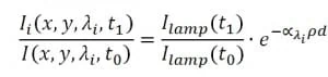
To avoid time variance, the imaging frame captures the culture chamber and a nearby empty area of the chip, which should not show absorption compared to the calibration measurements. Hence, the relative intensity in that area provides the ratio, i.e., the source’s intensity variation between calibration (t0) and measurements (t1). Repeating the procedure for both the absorption wavelengths of phenol red and thus dividing the two obtained values leads to the following:
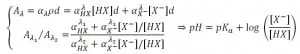
The natural logarithm of the previous expression gives the ratio between the two absorption coefficients of the phenol red. This ratio yields to the pH value of the cell culture environment using the following expression:
It is important to note that pH values depend on other factors, such as temperature and the particular cell culture medium employed. The device used is a PDMS microfluidic chip with 12 culture chambers and built-in valves for rinse and medium supply, the design of which was developed by Gomez-Sjober et al. [2].
Some commercially available bandpass filters (centered at 430 nm and 560 nm to match phenol red absorption peak) with 10 nm width were used to capture pictures at different wavelengths. The system is automated and can be operated via Matlab software.
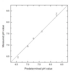
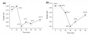
Figure 2 presents some results showing the reliability and reproducibility of pH measurements performed with this technique. The primary measurement bias source fluctuated between chambers due to imperfect rinse, incomplete flushing, and chemical traces. Furthermore, PDMS uptake of phenol molecules caused a continuous deviation over time, which can be addressed by introducing a time-dependent bias in pH measurements.
In conclusion, using standard life-science equipment, this method provides reliable and precise (max sensitivity < 0.005 for pH ≈7÷8) pH measurements through a simple set-up. Furthermore, it exploits small volumes of medium of the order of nL, thus reducing costs compared to conventional pH control methods. The main shortcomings are the unexpected bias on pH values due to the perfect rinse of the chambers and absorption medium uptake by the microfluidic device.
Measurements of pH using an hybrid EIS sensor /microfluidic device
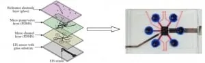
Lin et al. [3] developed a microfluidic device that monitors pH and glucose levels. In Figure 3, it is possible to admire a schematic showing the various layers of the chip. Starting from the bottom, an electrolyte-insulator-semiconductor (EIS) sensor is bonded to a glass substrate with a built-in aluminum electrode to conduct the sensing signal from the bottom of the EIS sensor.
Then, two PDMS layers are deputized for the fluidic handling of the sample. In particular, one layer hosts the microfluidic channels, whereas the other PDMS layer is built with six pneumatic pumps for flow regulation and sample loading.
It is essential to underline that these pumps also operate as valves: an automated compressed-air flow that deflects the PDMS layer onto the channels, thereby regulating or blocking the flow of the sample beneath. Finally, on the top of the device, an Ag/AgCl thin-film reference electrode is on a glass substrate to provide a reference potential for pH measurements.
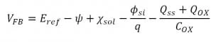
The theoretical principles exploited to monitor pH level are briefly described in the following. The flat band voltage of the EIS sensor is defined by the following expression:
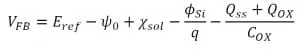
Where Eref is the reference electrode potential, Χsol is the surface dipole potential of the solution, Φsiis the silicon work function, q is the elementary charge, Qss is the surface state density per unit area at the silicon surface, Qox is the fixed oxide charge per unit area, Cox is the gate insulator capacitance per unit area, and Ψ is the surface potential.
In the previous expression, the only free parameter is the surface potential. Thus, the variation of the flat band potential of the EIS sensor is determined exclusively by changes in the surface potential and, thereby, by changes in the surrounding environment’s pH level.
To verify the performance of the system, four solutions with a known pH (4.03, 6.70, 7.40, and 9.57) have been injected inside the chamber.
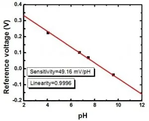
Figure 4 summarizes the results obtained [3]. The high linearity achieved (0.9996) indicates an efficient rinse of the chamber between the loading of different samples. Moreover, the system could operate using minimal reagent (~102 µL). Furthermore, all measurements were carried out automatically, thus avoiding any issue related to contamination due to manual handling.
Regulation of pH using a feedback-based microfluidic system
In this paragraph, another microfluidic device capable of pH monitoring is presented. Welch and Christen [4] developed this device to exploit a PDMS chip where fluids are managed, plus an ion-selective-field effect transistor (ISFET) for pH measurements. This device’s key feature is that it is capable of pH probing and can adjust the level automatically.
Indeed, in the PDMS chip (Figure 5), two reservoirs with basic (pH +) and acid (pH -) solutions are stored. The output of these chambers is controlled by two valves, which regulate the outgoing flow and, hence, the subsequent mixing, allowing active control over the pH of the mixed solution exposed to the ISFET sensor.
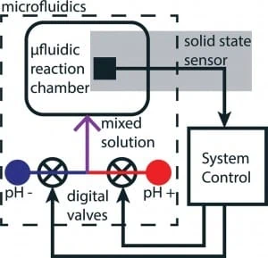
As has been said, the device is made out of PDMS via conventional soft lithography techniques. The polymeric structure lies upon a silicon substrate, which forms the microchannels’ base. These supply the reaction chamber, where the pH sensor is located, with an acid and a basic solution that mix at the junction of the two microchannels just before the chamber.
A third valve-less input channel is present to supply standard pH buffers for sensor calibration purposes. The same silicon substrate sustains the ISFET, which has two electrodes for reference and sensing.
A software controls the valves based on the sensor’s readouts. A proportional-derivate (PD) feedback control algorithm calculates an output signal to manage the pH level. This system has been proven to control the pH level of the solution in the reaction chamber inside the chip in real-time.
This was achieved by feedback-controlled stepping of 0.14 pH in both increasing and decreasing directions. Finally, the system can stably reach the pH setpoint within 20 seconds from the initial input of the operator.
Active pH control and regulation via a hydrogel-based microfluidic chip
Hydrogels are a category of materials that is growing in importance in biomedicine applications. Hydrogel is the name that indicates a matrix of polymers capable of trapping water molecules between the spaces of its polymeric chains. This feature allows them to change their morphology without any external power supply.
Furthermore, such materials are highly biocompatible and durable; hence, their application in file sciences is highly advantageous. In particular, the capability of shape and size change triggered by environmental parameter variations can make them a convenient material when aiming for pH control.
Atwe et al. [5] exploited this feature to design a microfluidic device that uses hydrogels as a micro-valve to control flows based on their pH. A pH-sensitive hydrogel has acid or primary groups, and ionization can be triggered by letting a medium of a particular pH flow through them. Such ionization leads to a flow of counter ions from surrounding regions into the gel, eventually resulting in water molecules equalizing the osmotic pressure between the two sides of the gel’s boundary.
Thus, to sustain this pressure gradient, the hydrogel expands accordingly to pH changes. This pH-dependent hydrogel expansion is the basic principle of creating a micro-valve in a microfluidic channel. Indeed, in Atwe’s device, slices of hydrogels have been packaged in the network of microchannels inside a PDMS chip so that the flow path could autonomously narrow or expand itself based on the pH of the flowing medium, thus allowing a pH-dependent flow regulation.
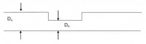
Figure 6 shows a schematic of the process: the medium pH causes the hydrogel to contract, thus reducing the diameter of the channel from Db to Da (Db < Da). Figure 7 shows the variation of the pores’ size due to ions uptake at various pH values. It has been found that the maximum variation occurs at pH = 3, where pores pass from an average diameter of 20 microns to an average diameter of 3 microns. Thus, it can be inferred that the pump’s maximum efficiency occurs when the flowing medium is at pH=3.
Supplementary notes
The modern conception of pH is due to Lavoisier and Arrhenius, who studied this chemical propriety more scientifically in the 18th century. Indeed, before them, the classification between “acid” and “base” was deputed to observable or sensed proprieties such as taste.
Arrhenius was the first to hypnotize that the pH value was related to the charge carriers in a given substance. In particular, he inferred that hydrogen ions carried the current in acid substances and hydronium ions in basic ones.
As of today, the official definition of pH is:
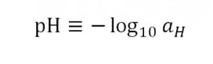
Where the argument of the logarithm is the activity of the hydronium ions on the molal scale. Moving over, in an electrolyte solution, the formula that relates the concentration gradient to the electric gradient is the Nerst equation:
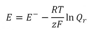
Where E is the potential of the electrolyte, E- is the standard potential, R is the universal gas constant, T is the temperature (in Kelvin), z is the number of moles of electrons transferred during the reaction, F is the Faraday constant and Qr is the reaction quotient. This equation is the basis of the implementation of solid-state sensors, such as ion-selective-field-effect-transistor (ISFET), for pH measurements (Figure 8).
Indeed, for these potentiometric ion sensors, i.e., sensors whose potential is measured as a function of ion concentration, the Nerst equation prescribes that the electrode potential is a direct logarithmic function of the ion activity in the electrolyte solution in which the sensor is immersed. The resulting equation for the flat band voltage of an ISFET is given by:
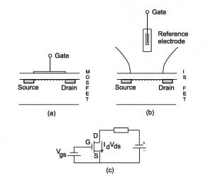
Where all terms are constant except ψo. This direct dependency of the ISFET potential from the surface potential makes ISFETs sensitive to the electrolyte pH. ISFETs are analogous to metal-oxide-semiconductor-field-effect-transistor (MOSFET), and they can indeed be schematized by the same equivalent circuit (Figure 9, c).
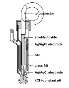
The macro difference between the two is that the metal gate of the MOSFET (Figure 9, a) is replaced by the metal of a reference electrode (Figure 9, b). A reference electrode is just a contact between a metal wire and an aqueous solution used to determine the electrical potential of this solution. In practice, a reference electrode consists, for instance, of a chloridated silver wire (silver with a coating of insoluble silver chloride) in a potassium chloride solution with a constant concentration.
The electrochemical couple thus formed results in a continual potential according to the Nernst equation. The inner solution of a reference electrode makes contact with the solution of which the electrical potential has to be measured using a barrier, the so-called frit. Note that the sensing material (the membrane) must be conducted for this type of potentiometric sensor because the measurement circuit must be “closed.”
In other words, the reference electrode stably pairs an electric field, penetrating the oxide into the “electronic world.” If the outer surface of the oxide is in equilibrium with an ionic solution in contact with the oxide, the resulting interfacial potential will modulate the electric field. Thus, a perfect and stable contact is provided between the “ionic world” and the “electronic world.”
Furthermore, in the case of ISFETS, the gate voltage is the voltage at the reference electrode, usually zero (grounded reference electrode). Still, the threshold voltage also contains terms that reflect the interfaces between the liquid and the gate oxide on one side and the fluid and the reference electrode on the other.
Therefore, designing a pH-sensitive ISFET with maximum sensitivity and selectivity requires a detailed investigation of the oxide-electrolyte interface to choose the best oxide, which is not a priori the silicon dioxide as used for MOSFETs.

Review done thanks to the support of the LAPASO project
FP7-PEOPLE-2013-ITN – Marie-Curie Action:
“Innovative Training Networks”
Author: Walter Minnella, PhD
Contact:

References
- E. B. Magnusson, S. Halldorsson, R.M.T. Fleming, K. Leosson. Real-time optical pH measurement in a standard microfluidic cell culture system. Biomedical optics express (2013), 4:1749-1758.
- R. Gómez-Sjöberg, et al. Versatile, fully automated, microfluidic cell culture system. Analytical chemistry (2007), 79.22:8557-8563.
- Y.-H. Lin, A. Das, M.-H. Wu, T.-M. Pan, C.-S. Lai. Microfluidic chip integrated with an electrolyte-insulator-semiconductor sensor for pH and glucose level measurement. J. Electrochem. Sci. (2013), 8:5886-5901.
- D. Welch, J. Christen. Real-time feedback control of pH within microfluidics using integrated sensing and actuation. Lab on a chip (2014), 14:1191-1197.
- A. Atwe, A. Gupta, R. Kant, M. Das, I. Sharma, S. Bhattacharya. A novel microfluidic switch for pH control using Chitosan based hydrogels. Microsystem Technologies (2014), 20:1373-1381.
As well as the articles cited in them