Pros and cons of different microfluidic flow sensor types: a review
What are the different flow sensor types already in the market? Is there any promising technology at the proof-of-concept stage? In this review, we answer these questions, providing tips on choosing the adequate flow sensor type for your experiment.
The expansion of microfluidics is partly due to the development of functional components, such as sensors handling fluids at the microscale. A complete microfluidic circuit requires measuring and controlling the sample dispensed volume and flow rate. Flow rate measurement and control can be achieved by combining a flow controller system with a flow sensor.
This review will look at the different flow sensor types available on the market and others still at a proof-of-concept stage. Throughout this review, we will discuss the advantages and limitations of each sensor. We will start with a small introduction to microfluidics and flow sensors.
We recommend reading the excellent review by Canaviol et al. [1] and Liji et al. [2] for a more in-depth comprehension of the different flow sensor technologies.
Microfluidic flow sensors
Microfluidics is both the science and technology that manipulate fluids at the scale of micrometers and manufacture microminiaturized devices. It can integrate numerous microchannels, each measuring mere micrometers, on a single chip that fits in your hand. This process enables the efficient handling of small volumes of fluids (e.g., reagents for biochemical reactions).
A microfluidic liquid flow sensor is designed to measure the flow rate of small quantities of liquid in microfluidic systems. Controlling the flow rate is possible by combining a flow controller system with a flow sensor in a microfluidic setup. Measuring flow rate is challenging due to the absence of a direct measurement technique. Nevertheless, various indirect methods are available, each with its own advantages and drawbacks.
Flow sensor types
Figure 1 and Table 1 summarize the different flow sensor types and some properties of the commercialized ones.

Table 1: A summary of some specifications of the available flow sensors in the market [1, 2].
| Types | Manufacturer | Flow Range (μL/min) | Relative accuracy (%) | Repeatability (%) | Response time (ms) |
| Thermal flow sensors | |||||
| Anemometry μ-FLOW | Bronkhorst | 0.08 – 167 | 20 – 5 | <0.2 | 10 – 20 |
| Calorimetric LD20-2600B | Sensirion | 0.07 – 1660 | 10 – 2.5 | 0.5 | 40 |
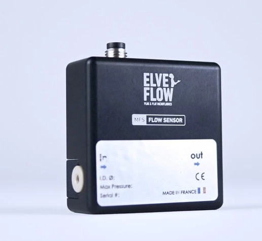
| Calorimetric Microfluidic flow sensor – MFS | Elveflow | 0.07 – 5000 | 10 – 5 | 0.5 – 1 | 40 |
| Time-of-flight LF6000 | Siargo | 0.5 – 6000 | 6 | 0.5 | 200 |
| Coriolis flow sensor | |||||
| Mini CORI-FLOW ML120 | Bronkhorst | 0.84 – 3300 | ± 0.2 | 0.05 | <200 |
| Cantilever | Micromotive mikrotechnik | 2 – 500 | 0.1 | 10 | |
| Differential pressure | |||||
| Pulsed flow sensor PFS-V4 | ReseaTech | 1 – 30 ml/min* | 1 – 2 | ||
*This differential pressure flow sensor measures flow rates in the order of ml/min, this range does not fit in the microfluidic range, but pretty close.
Active flow sensor types represent two-thirds of flow sensors used in microfluidics.
Active flow sensor types
Active sensors supply energy to the liquid to measure its disturbance. Thermal flow sensors and Coriolis sensors are considered active flow sensors. To determine flow rate, thermal sensors apply heat to the fluid, gauging the heat transfer, whereas Coriolis sensors stimulate the passing fluid, generating a force known as the Coriolis force.
So, let’s look closely at the different thermal flow sensing types.
Thermal flow sensors-Commercialized
Thermal flow sensor types are the most used sensors to measure flow rate. They are composed of a central heating element and one or two sensors. The sensing element detects the variation in heat transfer between the heating element and the surrounding fluid. Minimum ranges for microfluidic applications can reach 7 nl/min. Thermal flow sensors must be calibrated to each medium’s heat capacity and can transfer heat to the fluid during measurement.
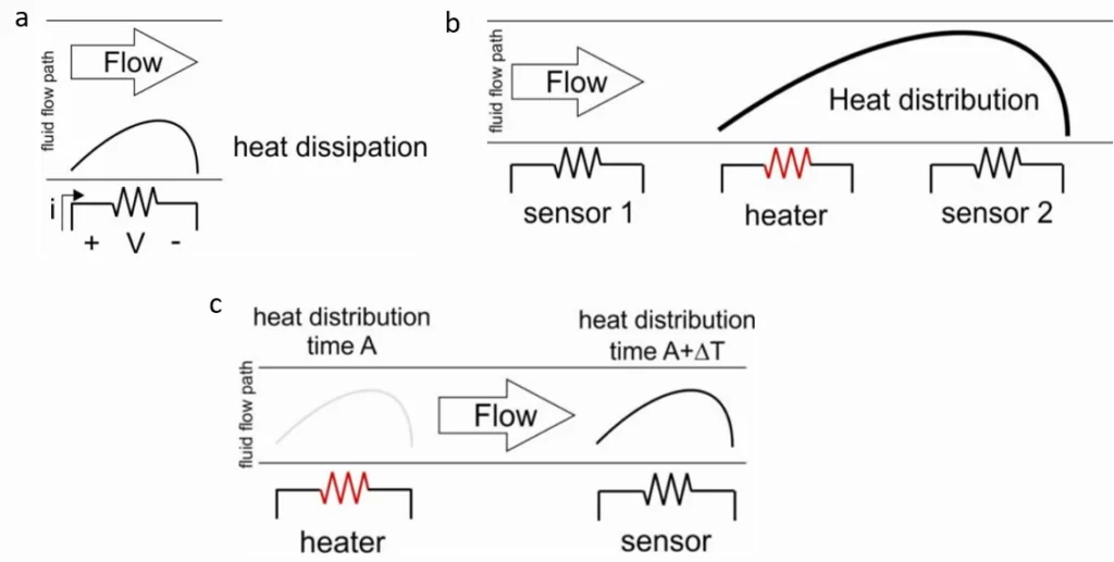
There are three main measurement methods for thermal flow sensing: Hot-wire anemometry, calorimetry, and time-of-flight (Figure 2).
Hot-wire Anemometry- Commercialized
Flow sensors based on the anemometry principle measure the effect of the flowing fluid on a resistive element, which also serves as the heater and the sensing element (Figures 2a – 3). Instead of measuring differences in the temperature profile induced by fluid flow at the central microheater through calorimetry, anemometry measures the heat loss attributed to forced convection.
These sensors can also function by quantifying the increase in the heating power required to sustain a consistent heater temperature. While this mode entails a feedback loop, it results in superior resolution and frequency response. However, this method has some limitations: it only measures a small flow rate range, has low sensitivity and high power consumption, and can’t identify flow direction.
Average range: 0.02 – 167 μL/min
Accuracy: 20 – 5 %
Calorimetry- Commercialized
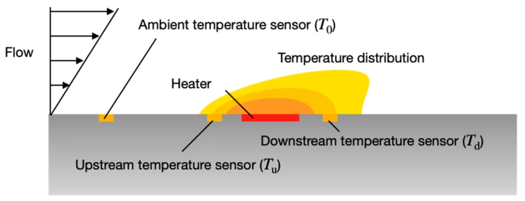
A calorimetric flow sensor measures the asymmetry of the passing fluid temperature profile by using two heat sensors surrounding a central heating element and a constant current applied to the heater (Figure 2b). In this case, the heat transfer depends on the volume flow rate. The sensor can measure bidirectionally if the two heat sensors are mounted on either side of the heating element (Figure 4). Calorimetric capillary sensors measure a shallow flow down to nanoliters per minute.
These sensors consume less power than hot-wire anemometry sensors, and they can determine the flow direction. However, their non-linearity and low sensitivity are two main constraints. The sensitivity can be increased by approaching the sensors from the heating element, which will result in higher production cost, or by increasing the temperature range, which is unsuitable for thermosensitive fluids.
To maintain a competitive price, manufacturers have reduced the channel’s internal diameter and defined it according to different flow rate ranges (An example of how the distance between the heater and sensors can be optimized is shown in Figure 5). However, the sensor diameter can be a limitation for the lowest flow rates.
Furthermore, measuring the flow rate above a certain threshold is impossible due to the limited heat transfer between the liquid, the sensor, and the heating element. However, the MFS flow sensor comprises five sensors that cover a flow rate range from 0.07 μL/min to 5 ml/min.
Average range: 0.07 – 5000 μL/min
Accuracy: 10 – 5 %
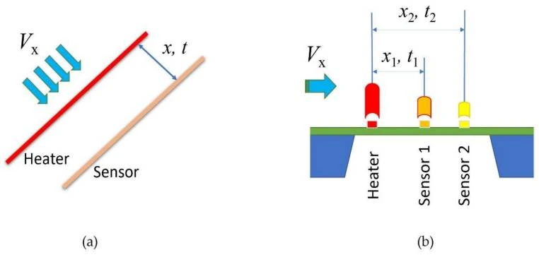
Time-of-flight- Commercialized
Flow sensors based on time-of-flight technology are less commonly used. They measure the transit time of a heat pulse over a known distance, defined by the heater and the sensor placed downstream, with the heater thermally isolated from the sensor (Figures 2c – 6a). This technique encounters the same sensitivity problem as in calorimetric sensors. Moreover, another limitation is that thermal diffusion can more easily mask the sensor signals at low flow rates, resulting in poor measurement precision.
Average range: 0.5 – 6000 μL/min
Accuracy: 6 %
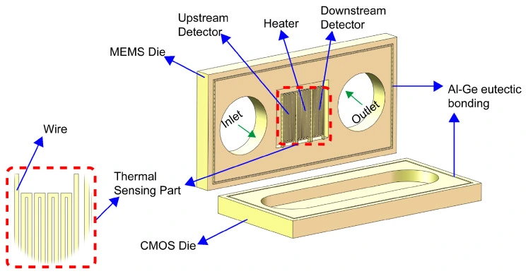
Microelectrochemical systems (MEMS) are the most mature technology for thermal flow sensors. It offered a low-cost, scalable, and small device footprint thermal flow meter with high sensitivity. The calorimetric principle is the most adapted to MEMS. The measurement requires a calibration step for each liquid used. In addition, a sensor measuring range varies according to the liquid thermal properties; for example, a MEMS thermal flow sensor can measure rates from 1 to 80 μL/min when flowing water but 20 to 500 μL/min for other liquids.
In addition, MEMS calorimetric sensors have the same limitations as conventional calorimetric sensors, mainly the saturation limit and low sensitivity, which were discussed above. Moreover, MEMS thermal flow meters are prone to clogging.
Compared to the traditional ones (Figure 6), micromachined time-of-flight sensors seem to have a less complicated heat transfer, a much lower power consumption, and a lower heat transfer into the fluid [7].
Now, let’s look closer at the Coriolis flow sensing type.
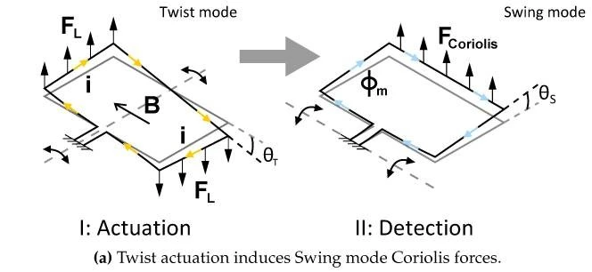
Mechanical Coriolis- Commercialized
The Coriolis flow sensors are resonators of one or several tubes oscillating thanks to an external exciter. The Coriolis force is an inertial force that deflects a moving fluid in a perpendicular direction, producing a modification detected by an external sensing system (Figure 7). This movement is correlated to the flow rate, and thus, fluid density can be simultaneously determined. MEMS technology contributed to the commercialization of the Coriolis sensor and its adaptation to microfluidics.
In contrast to a calorimetric sensor, flow rate measurement with a Coriolis sensor is over three orders of magnitude and is independent of the liquid properties. Another advantage is that it does not require any calibration step [8]. However, these flow sensor types are used for large-volume applications since the relatively weak Coriolis forces are more challenging to detect for small flows.
Moreover, the sensor’s temperature increases during measurement, which can be a limitation for thermosensitive liquids. Coriolis’ microchannel volume is reduced to measure hundreds of nl/min flow rates; thus, like MEMS thermal flow sensors, Coriolis’ microchannel is prone to clogging even with fine particles. The cost can be another issue since the Coriolis sensor is more expensive than thermal sensors.
Average range: 0.8 – 3300 μL/min
Accuracy: 0.2%
Passive flow sensor types
Passive flow sensor types represent one-third of flow meters used in microfluidics.
Passive flow sensor types do not supply energy to disturb the liquid. They are identified based on their transducing principle. The flow rate is measured through the sensor body deformation in flow meters with a fluid-structure interaction. In sensors with the gravimetric method, the mass of the flowing liquid is measured over time. Meters using the front-tracking meniscus method measure the flow rate in a capillary at the exit of the microfluidic circuit.
Fluid/structure interaction
The sensors based on fluid/structure interaction can be divided into subcategories depending on their measurement principle: cantilever bending, differential pressure measurement, and motion of seeded particles.
Cantilever- Commercialized
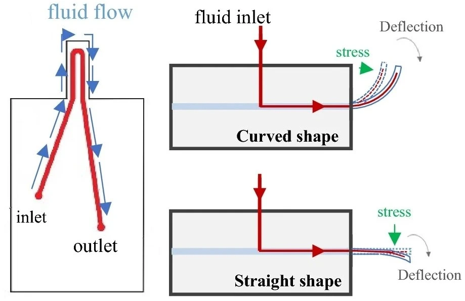
Cantilever-based flow sensors operate through the deflection of a cantilever in response to flow disturbances. The beam is positioned perpendicular to the flow and bends under the action of the fluid (Figure 8). The fluid’s motion generates a drag force, which can be calculated by integrating the stress on the beam’s surface, considering both pressure and viscous stress components.
Cantilever flow meters are categorized based on the bending degree of the cantilever underflow.
An entirely confined cantilever has the same size as that of the section. Holes were added to the cantilever, porosity was tuned, and mechanical properties were adapted to the varying measuring ranges. Flow rates are measured down to 2 to 35 μL/min.
Another cantilever geometry where the beam is confined in one direction, leaving most of the fluid flowing at its tip, was able to measure flow rates up to two orders of magnitude. The deformation is linear under a specific flow rate; the beam deflection increases more slowly.
The third geometry, where the cantilever is not confined, has been used to mimic hair cells or cilia. This geometry is most suitable for microfluidics. Compared to the other two geometries, the low confinement of the beam induces a moderately increased hydrodynamic resistance and a lower risk of clogging and allows the measurement of a broader range of flow rates.
Cantilever’s simple structure and function make it a favorable flow sensor type for microfluidic systems [10]. Cantilever manufactured with MEMS techniques are compact and in the same price range as thermal sensors. However, it requires a calibration step for thermal sensors. In addition, the test body is prone to contaminations, the mechanical properties of the beam covered with chemicals can be affected, and bending over a particular threshold force can become permanent.
Average range: 2 – 500 μL/min
Accuracy: 0.1 %
The following flow sensing techniques are not commercialized but are still in the proof-of-concept stage.
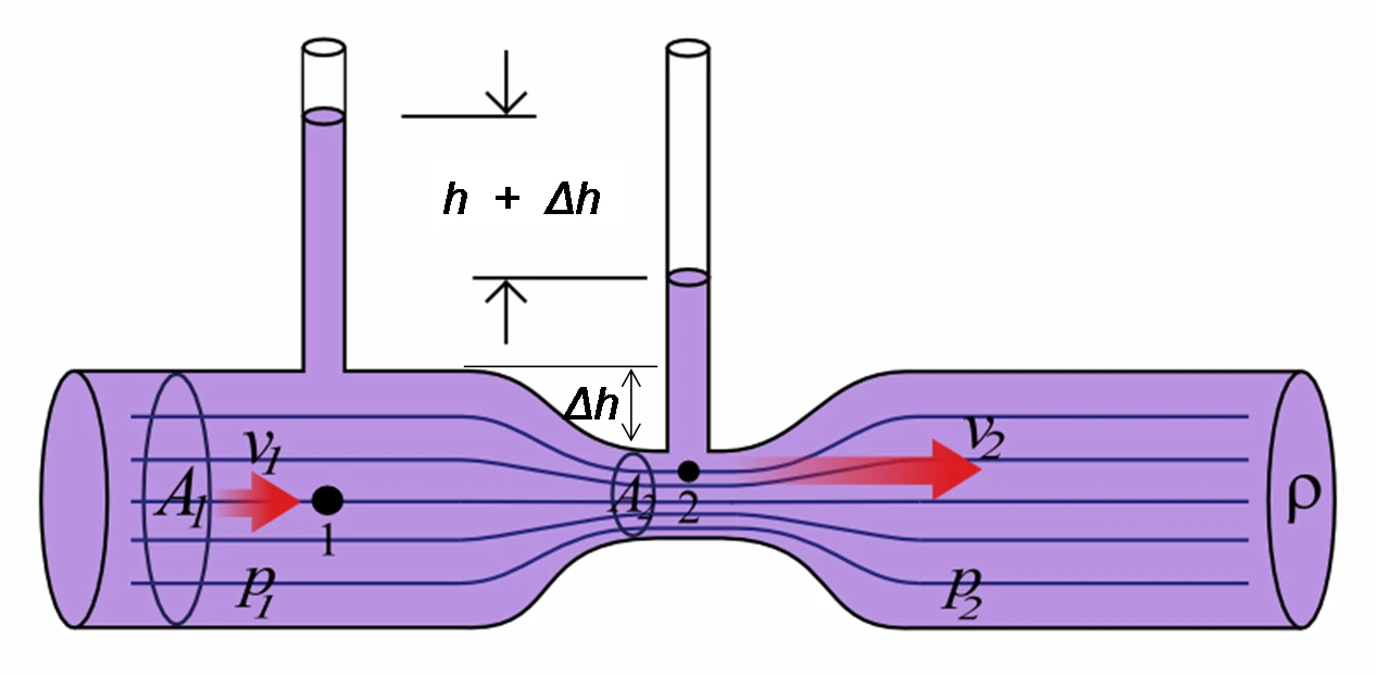
Differential pressure- Not commercialized
The hydrodynamic resistance is obtained from a calibration step. The integrated diaphragm will deform when pressure increases, resulting in a variation of the piezoresistive resistance. Another conformation is possible with two electrodes, one placed on the membrane and the other on the top. The membrane deforms, causing a decrease in the gap between the electrodes, which changes the electric capacitance.
This technology is widely used on the macroscale but remains a proof-of-concept at the microscale level. Contaminations in the sensor or fouling can affect the membrane’s channel geometry or mechanical properties, inducing a variation in hydrodynamic resistance and thus affecting the flow rate.
Tested Average range: 1.1 – 1100 μL/min
Obtained Accuracy: 10 % [11]
Particle seeding- Not commercialized
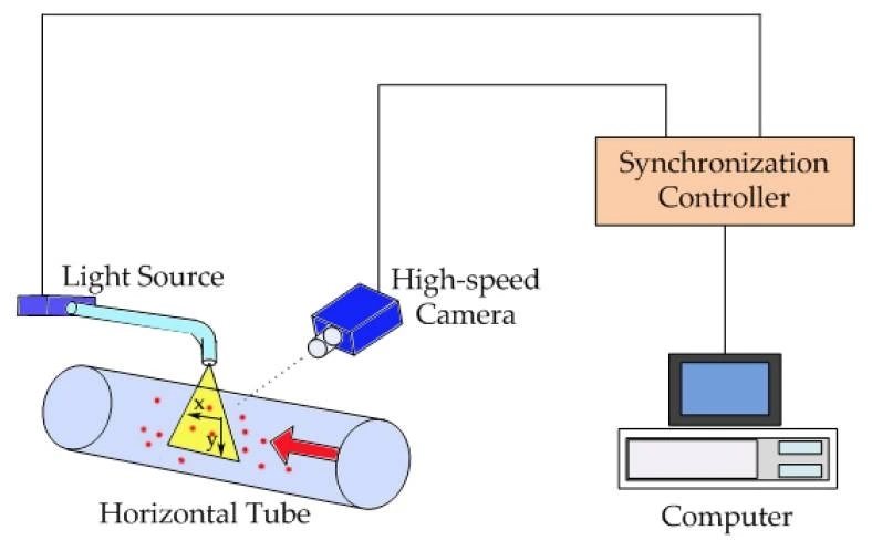
The particle seeding technique is based on measuring the velocities of particles seeded into the liquid. Thus, the flow rate can be determined. Electoral image velocimetry and laser Doppler velocimetry are measured using optical techniques.
The first is based on the cross-correlation of two scattering particle images to determine the most probable local displacement. A high-speed camera continuously takes images of the two-phase flow. By analyzing and processing the captured images, the vector displacement of the tracer particles between two successive frames is obtained (Figure 10). The flow rate is measured from the integral of the velocity profile [12].
The second technique is based on a parallel interference fringe system formed by two intersecting coherent laser beams (Figure 11). The complete velocity profile is determined by measuring the channel height to obtain the flow rate. However, this is not required while using the laser Doppler velocity profile sensor. In this sensor, the position and velocity of tracer particles are determined using two overlapping fan-like fringe systems. One system converges, while the other diverges along the optical axis.
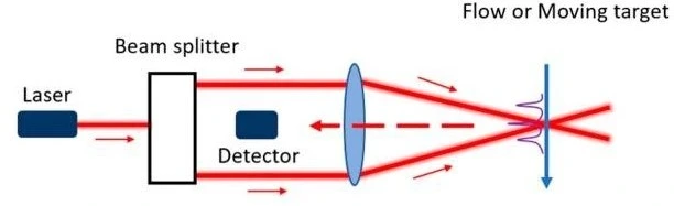
Techniques based on particle seeding are not commercialized end-user products mainly because of their large size and the particles. The optical devices accompanying these techniques are too voluminous and expensive to be integrated into a fluidic circuit. Nevertheless, particle seeding techniques are particularly suitable for sensor calibration.
Tested Average range: 0.001 – 54 μL/min
Obtained Accuracy: 2 – 5 % [14]
Gravimetry- Not commercialized
During calibration, hydrodynamic resistance and fluid density can be altered by tubing deformation, impurities, or varying temperatures. Evaporation must also be considered, especially when approaching nl/min flow rates. Preventing external vibration and testing environmental control is also critical to ensure the measurement is repeatable and accurate [15].
Tested Average range: 0.017 μL/min – 167 mL/min
Obtained Accuracy: 6 – 0.05 %
Front tracking meniscus- Not commercialized
The tracking meniscus technique was developed in response to the limitations of the gravimetric method. The front-tracking meniscus method is based on tracking the meniscus displacement of a flowing liquid in a known dimensions capillary set at the outlet of the calibration system (Figure 12).
A high-speed camera acquires images of the moving meniscus. It constitutes a calibration system adapted to microfluidics; however, its applications as a sensor are limited. This is due to its portability, which does not meet the dimensioning of a microfluidic experiment and can only be set at the outlet of the microfluidic circuit.
Tested Average range: 0.005 – 100 μL/min
Obtained Accuracy: 5 – 2 % [16, 17]
Conclusion – Carefully choose your flow sensor type
To control your microfluidic circuit perfectly and have a hand on the flow rate variations, it is crucial to correctly choose the flow sensor to be integrated with the flow controller. The different flow sensor types have been developed in academic laboratories, but most have not yet led to end-user products. Commercial flow meters based on thermal, Coriolis, and cantilever principles are already on the market, with thermal and Coriolis sensors being the most used in microfluidics.
Many techniques from those mentioned in this review are used to acquire microfluidic thermodynamic properties such as viscosity, density, solubility, and phase equilibrium directly from the channels. However, many are bulky, costly, and not easily integrated with the channels.
Moreover, the available flow sensor types are insufficient to catch up with the progress of microfluidics and cover the needs of current life science applications, especially for measuring wide-range flow rates while maintaining accuracy at low flow rates down to nl/min. Furthermore, most of the described flow sensor types require a specific calibration step, which depends on the fluid properties.
The ideal flow meter does not exist yet on the market. However, you can choose the adequate one that best suits your experiment or application from what is already available.
This review was written under the European Union HORIZON-EIC-2022-TRANSITION-01, grant agreement No. 101113098 (Galileo).
This review was written by Celeste Chidiac in October 2023.
References
- Kartmann S, et al. MFMET A1.1.1 Literature and market research: definitions, characteristics, specifications, application and function of flow control components. 2022.
- Cavaniol C, et al. Flowmetering for microfluidics. Lab on a Chip. 2022;22(19):3603-3617.
- Kuo J, L Yu, and E Meng. Micromachined Thermal Flow Sensors—A Review. Micromachines. 2012;3:550-573.
- Doh I, Sim D, and Kim SS. Microfluidic Thermal Flowmeters for Drug Injection Monitoring. Sensors. 2022;22(9):3151.
- Murakami K, et al. Development of a Flexible MEMS Sensor for Subsonic Flow. Micromachines. 2022;13(8):1299.
- Qi J, et al. Investigation on the Effective Measures for Improving the Performance of Calorimetric Microflow Sensor. Sensors (Basel). 2023;23(17).
- Huang L. Micromachined Thermal Time-of-Flight Flow Sensors and Their Applications. Micromachines (Basel). 2022;13(10).
- Groenesteijn J. Microfluidic platform for Coriolis-based sensor and actuator systems. 2016.
- Schut T, Wiegerink R, and Lötters J. μ-Coriolis Mass Flow Sensor with Resistive Readout. Micromachines (Basel). 2020;11(2).
- Mohammadamini F, Rahbar Shahrouzi J, and Samadi M. A suspended polymeric microfluidic sensor for liquid flow rate measurement in microchannels. Sci Rep. 2022;12(1):2642.
- Rodrigues T, Galindo-Rosales FJ, and Campo-Deaño L. Towards an Optimal Pressure Tap Design for Fluid-Flow Characterisation at Microscales. Materials (Basel). 2019;12(7).
- Han L, et al. Particle Image Velocimetry of Oil-Water Two-Phase Flow with High Water Cut and Low Flow Velocity in a Horizontal Small-Diameter Pipe. Sensors (Basel). 2019;19(12).
- Li Y, Dieussaert E, and Baets R. Miniaturization of Laser Doppler Vibrometers-A Review. Sensors (Basel). 2022;22(13).
- Salipante P, et al. Microparticle tracking velocimetry as a tool for microfluidic flow measurements. Experiments in Fluids. 2017;58(7):85.
- Liji H, Microfluidic Flow Sensing Approaches, in Advances in Microfluidics and Nanofluids, S.M.S. Murshed, Editor. IntechOpen: Rijeka. 2021;Ch.4.
- Batista E, et al. New EMPIR project – Metrology for Drug Delivery. Flow Measurement and Instrumentation. 2020;72: 101716.
- Ahrens M, et al. Design and uncertainty assessment of a setup for calibration of microfluidic devices down to 5 nL min −1. Measurement Science and Technology. 2014;25:015301.